Three (3) Phase DOL Starter
Working principal, Parts, control circuit and Connection diagram.
1- 3 Phase Direct On Line (DOL) Starter:
Three phase direct on-line starters are commonly used for small capacity motors like as up to 5 HP. It is used a lot of for motor start and stop in safely condition as overload and short circuit protection. It is very simple and low-cost product. Due to low price, it is very famous for using low-capacity motors.
2- Wiring diagram of 3 Phase DOL Starter.
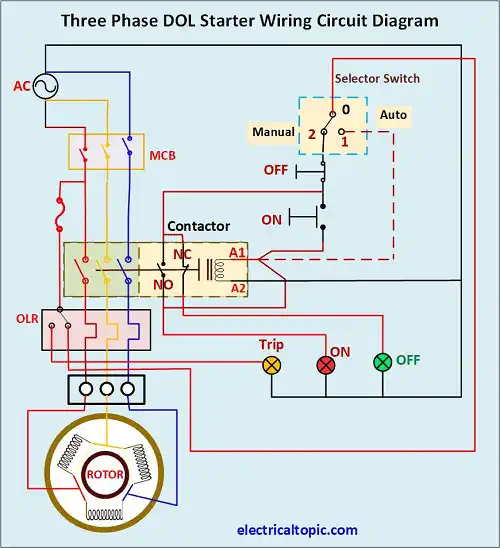
3- Working principal of 3 Phase DOL Starter.
Three phase direct on-line starter is used for operating up to 5 HP capacity motor. two type mode of operation are used like as manual mode and auto mode.
1- Manual Mode:
In this mode start and stop button are used. Working principle was defined below mentioned points.
- Before start, check the voltage as per standard.
- Press the start push button then contactor coil will be energized. Due to electromagnetic induction, the contactor will be hold and motor will start.
- After holding contactor auxiliary contact NO will be converted into normal close (NC). Holding supply of contactor coil is received from input terminal of start button and coil will hold continue after getting free from pressing start button.
- Motor will take a heavy current in starting period but speed will increase and current also decrease. After getting full speed the motor will take normal current as per load.
- Motor overload relay will check running load as per load setting on relay. If the load is more as set load, then control supply will be braked by overload relay and motor will stop.
- If we want to stop the motor then we will have to press the stop button after that the contactor coil will be de-energized. Contactor terminal points will be disconnected and motor will stop.
2- Auto Mode:
In this mode auto selector switch is selected in auto mode. Working principle was defined below mentioned points.
- Before start, check the voltage as per standard.
- Select the selector switch in auto mode then contactor coil will be energized. Due to electromagnetic induction, the contactor will be hold. Motor starts running.
- After holding contactor, the holding supply of contactor coil is received from terminal of selector switch and coil will hold continue.
- Motor will take a heavy current in starting period but speed will increase and current also decrease. After getting full speed the motor will take normal current as per load.
- Motor overload relay will check running load as per load setting on relay. If the load is more as set load, then control supply will be braked by overload relay and motor will stop.
- If the power supply is switched off then the contactor coil will be de-energized. Contactor terminal points will be disconnected and motor will stop.
- If we want to stop the motor then we will have to select the selector switch on neutral mode or off mode then the contactor coil will be de-energized. Contactor terminal points will be disconnected and motor will stop.
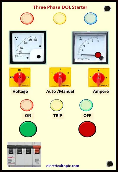
4- Parts of Three Phase DOL starter:
1- Electrical panel body:
It is made with mild steal as box type with cover. In side box is used for main working parts like as miniature circuit breaker (MCB), Contactor, overload relay, control MCB, Connection plate etc.
Box cover is used for controlling parts like as start, stop push button, indicators, voltmeter and amp meter, auto manual selector switch. Starter panel size can be varied as per capacity.
2- MCB:
It is miniature circuit breaker.it is used for controlling incoming power supply. Different type MCB are used in electrical system but for direct on-line starter the TPN MCB are used which is donate for three phases and neutral as R, Y, B, N.
3- Single phase preventer.
It is known as protection device for detecting all three phase power supply. if any phase is disconnected as accidentally then it detects and stop the motor. it can be reset as manual after checking power supply.
4- Contactor.
It is used as switch for incoming and outgoing power supply to the motor. it is controlled with low voltage coil whichis operated 24 and 230 voltages for making and breaking power supply to the motor.
5- Overload relay.
Overload relay is used for motor protection from overload and short circuit. It is installed after main contractor. It has many loads settings sot that according requirement load can be set as per motor actual load. After tripping motor, the overload relay can be reset.
6- Fuse or control MCB:
Controlling MCB is used for control circuit, R phase MCB is used for protection of voltage measuring circuit. As same type Y phase and B phase MCB are used for protection of voltage measuring circuit. As per capacity it can be used single pole 2amp or 5amp.
7- Indicators.:
Indicators are used for getting status of starter which is on, off or trip, power supply R, Y and B phase. It is available in market for different color codding.
Indicator indicates of panel status in different color codding as red, blue, yellow, ambler, green etc. It is available or used in 110 voltage or 230 voltage power supply.
8- Amp and volt meter:
Measuring meters are used for measuring voltage and current. it is available in two types one is analogue type and other is digital type. Analogue meter is used separately but digital type meter only one.
9- Selector switch:
Selector switch is used for selecting auto and manual mode start of starter, voltage selector switch, amp selector switch. Voltage selector switch can be used for phase vise voltage selecting and amp selector switch is used of phase wise current measuring in amp meter.
10- Push button.
Push buttons are used for starting and stopping of starter. Start push bouton is green color and stop push button is red color.
11- Connection plate.
It is known as terminal plate or connector plate. It is made by Bakelite and available in according current ratings.