Three Phase Star delta Starter
Working principal, Parts and Connection diagram
1- Three Phase star delta Starter:

Induction motors are used commonly a lot of in the world. The starter is used for motor protection and safe operation. Two types of starters are used in commonly direct online starters and star-delta starters. DOL is used below 5 HP and star-delta starter is used above 5 HP.
When we start an induction motor then it draws a large current from the line against the normal current. At the time of starting the rotor works as a short circuit secondary so for running the rotor a more amount of induction torque is required.
During motor starting a large current will draw from the line. below 5 HP motor current can be bear but above 5 HP motor current cannot be bear because the line can be damaged or short.
For reducing the flow of starting current, a star-delta starter is mainly used in a three-phase induction motor. The concept is very clear that phase voltage is lower in star connection comparison of delta connection. In the star connection for reducing starting current, the starting voltage is reduced.
So, in this way, in star connection, the current is reduced. As per the delta connection, the motor takes normal current as per load.
2- Wiring diagram three phase star delta starter.

3- Working principal of three phase star delta starter.
Star delta starter is commonly used for three-phase induction motor. it is used for above 5 HP motors. It works in two functions one is star connection and the second is delta connection. In star connection, the voltage is reduced and delta is used for normal voltage. It can be operated in auto and manual mode.
1- Manual Mode:
In this mode start and stop buttons are used. Working principle was defined below mentioned points.
- Before starting, check the voltage as per standard.
- Press the start pushbutton then the star contactor coil will be energized. Due to electromagnetic induction, the star contactor will hold.
- After holding the star contactor auxiliary contact NO (normal open) will be converted into the normal close (NC). Holding supply of contactor coil is received from the input terminal of start button and coil will hold continue and start push button will free from pressing.
- Same time the power supply is received from the star NO output point and is connected into the main contactor holding coil through delta NC auxiliary contact. After that main contractor is held.
- Main contactor power supply and star contactor power is received in motor and motor starts. Due to low voltage as one-third the motor moves slowly and also starting load will be decreased.
- After crossing the set time, the timer changes the power supply star to delta connection, and the delta holding coil receives holding power through star NC points.
- During timer changing connection star to delta, the star contactor is stopped and delta is started. Now the motor is moved at normal speed in delta connection and it will take normal current.
- The power supply is received in holding coil of the delta through star NC point from timer.
- Motor will take a heavy current in starting period but it is reduced in star connection. after changing connection in delta, the motor speed will increase. After getting full speed the motor will take normal current as per load.
- Motor overload relay will check running load as per load setting on the relay. If the load is more as set load, then the control supply will be braked by the overload relay and the motor will stop.
- If we want to stop the motor then we will have to press the stop button after that the contactor coil will be de-energized. Contactor terminal points will be disconnected and the motor will stop.
2- Auto Mode:
In this mode, the auto selector switch is selected in auto mode. The working principle was defined below-mentioned points.
- Before starting, check the voltage as per standard.
- When the selector switch is moved in auto mode then the power supply is provided to the timer and start contactor holding coil.
- The timer provides a controlling supply to the star connections first.
- Same time the power supply is received from the star NO output point and is connected into the main contactor holding coil through delta NC auxiliary contact. After that main contractor is held.
- Main contactor power supply and star contactor power is received in motor and motor starts. Due to low voltage as one-third the motor moves slowly and also starting load will be decreased.
- After crossing the set time, the timer changes the power supply star to delta connection, and the delta holding coil receives holding power through star NC points.
- During timer changing connection star to delta, the star contactor is stopped and delta is started. Now the motor is moved at normal speed in delta connection and it will take normal current.
- Motor will take a heavy current in starting period but it is reduced in star connection. after changing connection in delta, the motor speed will increase. After getting full speed the motor will take normal current as per
- Motor overload relay will check running load as per load setting on the relay. If the load is more as set load, then the control supply will be braked by the overload relay and the motor will stop.
- If we want to stop the motor then we will have to press the stop button after that the contactor coil will be de-energized. Contactor terminal points will be disconnected and the motor will stop.
4- Parts of three phase star delta starter:
1- Electrical panel body:
It is made with mild steal as box type with cover. In side box is used for main working parts like as miniature circuit breaker (MCB), Contactor, overload relay, control MCB, Connection plate etc.
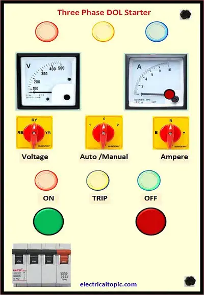
Box cover is used for controlling parts like as start, stop push button, indicators, voltmeter and amp meter, auto manual selector switch.Starter panel size can be varied as per capacity.
2- MCB:
It is miniature circuit breaker.it is used for controlling incoming power supply. Different type MCB are used in electrical system but for direct on-line starter the TPN MCB are used which is donate for three phases and neutral as R, Y, B, N.
3- Single phase preventer.
It is known as protection device for detecting all three phase power supply. if any phase is disconnected as accidentally then it detects and stop the motor. it can be reset as manual after checking power supply.
4- Contactor.
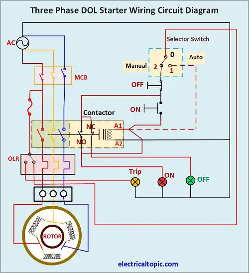
It is used as switch for incoming and outgoing power supply to the motor. it is controlled with low voltage coil which is operated 24 and 230 voltages for making and breaking power supply to the motor.
5- Overload relay.
Overload relay is used for motor protection from overload and short circuit. It is installed after main contractor. It has many loads settings sot that according requirement load can be set as per motor actual load. After tripping motor, the overload relay can be reset.
6- Fuse or control MCB:
Controlling MCB is used for control circuit, R phase MCB is used for protection of voltage measuring circuit. As same type Y phase and B phase MCB are used for protection of voltage measuring circuit. As per capacity it can be used single pole 2amp or 5amp.
7- Indicators.:
Indicators are used for getting status of starter which is on, off or trip, power supply R, Y and B phase. It
is available in market for different color codding.
Indicator indicates of panel status in different color codding as red, blue, yellow, ambler, green etc. It is available or used in 110 voltage or 230 voltage power supply.
8- Amp and volt meter:
Measuring meters are used for measuring voltage and current. it is available in two types one is analogue type and other is digital type. Analogue meter is used separately but digital type meter only one.
9- Selector switch:
Selector switch is used for selecting auto and manual mode start of starter, voltage selector switch, amp selector switch. Voltage selector switch can be used for phase vise voltage selecting and amp selector switch is used of phase wise current measuring in amp meter.
10- Push button.
Push buttons are used for starting and stopping of starter. Start push button is green color and stop push button is red color.
11- Connection plate.
It is known as terminal plate or connector plate. It is made by Bakelite and available in according current ratings.