Single Phase Energy Meter
Connection Diagram, Working Principle and Features.
1 - What is the Single Phase Energy Meter:
Single phase energy meter basicly two wire, phase and neutral of AC power consumption measuring device which is used for measuring power consumption in residential or domestic.It is also power consumption instrument device for measuring single phase electrical energy in residential societies of domestic or global. The electrical energy which is utilized by electrical load. It measures only utilized KWH power.

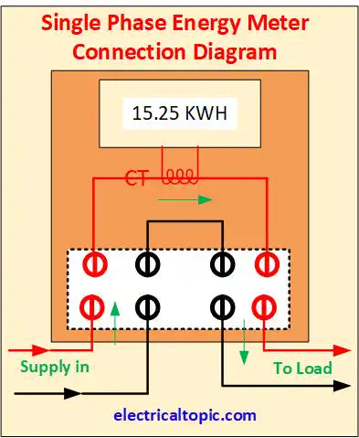
2 - Connection Diagram or Circuit Diagram:

3 - Working Principle:
Static energy meter works on digital integration operating principle. It has no moving parts and it is also
known as digital meter. The meter output is directly proportional to the digital pulse.
Input single
phase supply is connected to the input terminal and out terminal is connected to the load. A phase wire is
connected to meter input terminal and input terminal is connected to the output terminal through current
transformer. Neutral is connected to the directly.
The CT output wire is connected to the digital
board. The digital board output is provided to the counter mechanism motor which move the counter as per load in kwh unit.
4 - Specification of SP Energy Meter:
- Supply voltage : 240 V
- Frequency : 50 Hz
- Current : 0 to 40 Amp.
- Class : 1.0
- Meter Constant : 3200 pulses /unit
- Display : Seven segment LCD display
5 - Applications of SP Energy Meter:
- Residential houses
- Commercial building
- Residential societies
- For single phase industrial equipments as motors, AC etc.