PCC (Power control Center) Panel
Design, Diagram and Components.
1- What is the full form of PCC panel?:
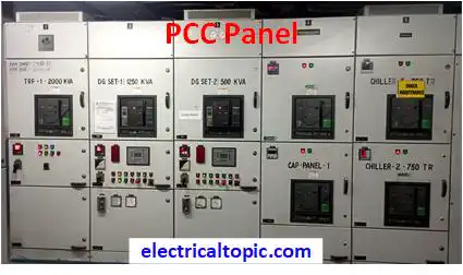
PCC control panel full form is Power control center panel.It is used for power receiving from various sources and distributed with controlling and monitoring voltage, load and safety.As per industries requirement diffrent types PCC panels are used.
2 - What is the PCC panel?
PCC panels are used for supervise and control the power supply in a large industries or high rise buildings. Many power sources can be used for receiving of power supply and can be distributed as per requirement of power. In other words we can say as power management system.

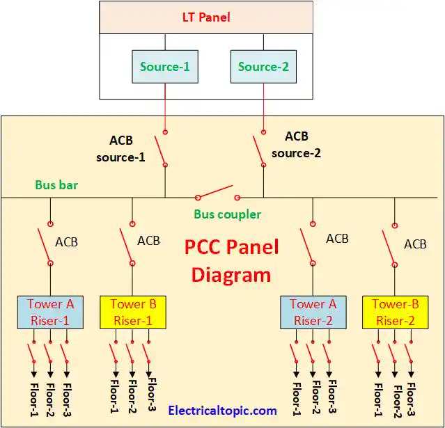
3 - Circuit Diagram or single line diagram of PCC panel:

4 - Components of PCC Panel:
1- Metering Section
Measuring meters are used for measuring the system parameters like as volt meter, amp meter, multifunction meter etc.
A- Measuring meters
Many types meters are used in panel like as Analog meter and digital meters. Amp meter, volt meter, multi function meter, energy meter are used for measuring the parameters. It all can be used digital or Analog as per requirement.
B- Indicators
Indicators are used for knowing the status of panel operation.Difference type indicators are used with different color.
- R Phase.
- Y Phase.
- B Phase.
- Breaker ON.
- Breaker OFF.
- Breaker Trip.
C- Selector Switches
- Amp selector switch
- Voltage selector switch
- TNC switch
2- Supply incomer Section:
Two nos supply source incomer are available and connected with busbar. If one supply source is problem then
other source can be connected with the help of buscuppler.
Air circuit breaker are used for making and
breaking supply.
3- Outgoing feeder section:
Outgoing feeder are used for distributing power supply like as high riser tower-1 a side, tower-2 b side etc. Air circuit breaker are used for making and breaking supply in outgoing feeders.
4- Bus Coupler Section:
Bus coupler are used for eliminating incomer sources each other. If one source is not working then other source can be connected with the help of buscuppler.
5 - What is the Diffrence between PCC panel and MCC Panel?:
1- PCC Panel:
PCC control panel is used for Master power control center where power supply is received from various sources and distributed into varius requred feeders.It is availabel in market diffrent typs as per power loads and requirement.
2- MCC Panel:
MCC control panel is full form is motor control center where varius motor control panel are controlled in a single large panel.