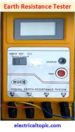
Earth Resistance Digital Meter
Connection Diagram, Working Principle and Features.
1 - Earth Resistance Meter:
Earth resistance meter is a instrumental device which is used for measuring the earth pit resistance. Charging battery is used for operating it.

The all electrical equipment like as domestic or industrial are grounded with earthing electrode. Equipment
and human is protected from any fault like as short circuit or other fault.
Low resistance value of
earthing means the earthing is good because the fault current will pass into ground quickly.
Earthing value should be less than 2 ohm but after passing time the value can be increase. So for checking
earth resistance value, the earth resistance meter is used.
2 - Connection Diagram:

3 - Working Principle:
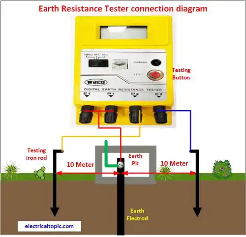
The main function of earth resistance meter is to measure the value of earth resistance. As per earth testing
connection diagram, two nos iron rod is installed with the distance of each 10 meters from earth pit. Earth
pit electrode is connected to the E1 and P1 terminal of meter. E2 is connected to the iron rod 1 and P2 is
connected to the iron rod 2.
After connection the testing button is pressed and the value is displayed.
If the value of earth resistance is below 2 ohm then it will ok. If the value is more than 2 ohm then the
earth pit electrode will have to maintenance.
4 - Features of Resistance Meter:
- Display: 3 1/2 digital
- Chargeable battery
- More than 25 MΩ between electrical circuit.
- Testing kit : 18 inch 4 nos iron spike, 1 nos hammer, 1 screwdriver set, 4 nos 25 feet cable with holding bag.
5 - Applications of Resistance Meter:
It is designed for measuring earth resistance of earth pit and it is used in Domestic and Industrial electrical installations. telecommunications and railway Electrification. It measures the ground resistivity and measures directly the resistance of the earth. It is easy to use and hand held instrument.