Generator AMF- Automatic Mains Failure Panel
Wiring diagram, Working Principle and Components.
1 - What is the AMF- automatic mains failure Panel:
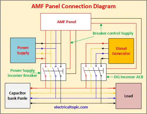
Auto panel is used for making or breaking power supply in automatic mode. Two nos power supply source, EB and DG are used in this panel.When the power supply cut is detected then the DG supply is connected in auto mode.

2 - AMF Panel Wiring Diagram:

3 - AMF Panel Working Principle :
When the AMF panel senses that mains has failed then it provides a start signal to the DG. After starting the
DG, the breaker is connected to the load. This all activity has been done in automatically.
When backup supply is detected then AMF panel sends a tripping signal to the DG breaker after tripping DG
breaker a other signal is sent to the EB supply breaker resultant the mains supply is resumed.
4 - What are the main components of AMF panel:
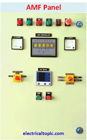
1- Metering Section
Measuring meters are used for measuring the system parameters like as volt meter, amp meter, multifunction meter etc.
A- Measuring meters
Many types meters are used in panel like as Analog meter and digital meters. Amp meter, volt meter, multi function meter, energy meter are used for measuring the parameters. It all can be used digital or Analog as per requirement.
B- Indicators
Indicators are used for knowing the status of panel operation.Difference type indicators are used with different color.
- R Phase.
- Y Phase.
- B Phase.
- DG ON.
- DG OFF.
C- Push button
- DG start
- DG stop
- Emergency switch
D- Selector Switches
- Amp selector switch
- Voltage selector switch
- Auto/manual
2- AMF controller:
AMF control relay is used for controlling the AMF panel. Monitoring relay is used for sending tripping and connecting signal. Voltage and current parameters are monitored by this relay. DG parameters are also monitored by this rely