HT Current Transformer
Connection diagram, Working Principle and Types.
1 - Full form of HT 11/33 KV CT-current transformer.:
HT: High Tension - 11 KV or 33 KV power supply .
CT: Current Transformer - It is used for current or load measuring for utilisaion unit.
2 - What is the HT CT-current transformer? :
A Current Transformer (CT) is an instrument transformer. It is used for providing a current in the secondary
winding. This secondary current is proportional to the primary alternating current which is passing in the
primary. Secondary winding current is as low current as 1-5 ampere with the same ratio in the primary.
This current is used in metering and protective relay. Different type of CT is used in the electrical system
as capacity and voltage of HT CT and LT CT.
Types of Current Transformer.
According to application and range of voltage, the CT can be classified into different types:
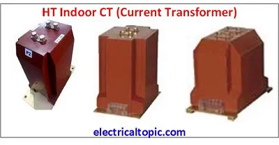
- HT CT. It is designed as per voltage.
- Indoor Type: Indoor type CT is used in HT panels inside substations or industries which is used in 11 KV or 33 KV high voltage. It is made of an epoxy cast resin material. It is known as a dry type Current Transformer.
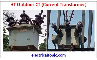
- Outdoor Type: it is used in a substation open above area 33 KV for transmission and
distribution.
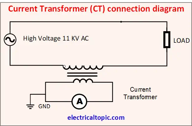
3 - HT current transformer(CT) : Connection diagram.
4 - Working Principle of HT Current Transformer.
The Current Transformer and Power transformer both are the same working. Same as the power transformer, CT
has
two winding primary and secondary. Primary is used for input supply and secondary is used for output supply.
Whenever the primary winding is connected to the input supply then induced emf produces in the secondary
winding. When we check the load impedance in 2ndary winding is very low. The CT is operated as a short
circuit
secondary so it depends on flowing primary current, not in a load impedance.
CT ratio is calculated according to ratio if the primary winding is 100 amp then the secondary ratio will be
one amp to five amp. We can divide 100 into 5.
1A =20 A, 2A =40 A, 3A =60, 4A =80 A, 5A =100 A.
Note: -CT secondary should not be open because CT primary depends on load, not in CT
secondary. It will be open.
5 - Technical Parameters of CT:
| Sr.No. | Parameters | Value |
|---|---|---|
| 1 | Voltage ratings: | 11 KV to 36 kV |
| 2 | Insulation Rating (kV) | Up to 36/70/170 KV |
| 3 | CT Accuracy Ratings | .1,.2,.5, 1, 3, 5 |
| 4 | Secondary Current Rating (A) | 1A or 5A |
| 5 | Current Rating of Primary (A) | Up to 3000A |
| 6 | Type of CT | Primary Wound Type |
| 7 | Rated Burden (VA) | Up to 30VA |