RTCC Panel in Transformer
Working function and circuit diagram.
1- Full form of RTCC Panel:
RTCC panel means remote tap changer control panel. It is used as remotely for controlling of the OLTC tap changing process in auto or mannual mode.
2- What is the RTCC panel in transformer?
RTCC panel means Remote Tap Control Changer. It is used in transformer for operating and controlling the transformer OLTC section through providing tap increasing and decreasing signal in auto mode or manual mode. RTCC panel is connected and synchronized with OLTC for remotely used without touching transformer danger HT voltage.
Transformer is a high voltage electrical device so many times the incomer voltage is increased or decreased from sub substation side so high voltage or low voltage according system default value may be dangerous for system. In that situation voltage will have to maintained so transformer voltage will have to maintained as remotely through RTCC panel in safe condition.
3- RTCC Panrel Working function.
RTCC panel is used for voltage regulation on remote mode or auto mode in transformer. It is used two types auto and manual mode. Voltage is controlled by in auto mode by automatic voltage regulation relay. The voltage can be regulated by manual mode with the help of push button and selector switch.
A- RTCC Operate in Auto Mode:
- the output voltage of transformer low tension (LT) side is monitored by voltage regulating relay. Standard Voltage should be 433 in output side.
- If the output voltage is low as per standard than tap changing drive motor will be moved by automatic voltage regulator (AVR) relay forwarding voltage. After getting required voltage, AVR relay will stop the sending voltage to the motor drive.
- If the output voltage on LT side is high than AVR relay provides signal to the reverse contactor relay resultant the motor drive is moved in reverse side and output voltage is maintained. After maintaining the voltage, AVR relay will stop the command.
B- RTCC Operate in Manual Mode:
In this mode we can regulate the voltage on manual mode
- If we want to decrease the voltage than we will select the selector switch on manual mode after that we will have to press low push button continue till required voltage.
- If we want to increase the voltage than we will select the selector switch on manual mode after that we will have to press high push button continue till required voltage.
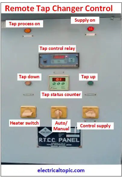
2- Parts of RTCC Panel:
1- Indicators.
Two indicators are used for as one is taping process and other is panel supply on or off. When taping process is working then show on condition. If the control supply of panel is available or not available then it shows the status.
2- Tap control relay.
Tap control relay is a voltage monitoring and default voltage maintaining relay. It works on auto mode. First it senses on line voltage if the voltage is low or high in comparison of default line voltage then it sends a commands to OLTC motors which is moved reverse or forward.
3- Tap status counter.
Tap status counter is a tap counting current status monitoring device. The status supply is received from tap control monitoring relay and then it shows the status of taping on display. Mostly seventeen nos taping are used for voltage variation.
4- Push buttons.
- Tap Up. When the voltage is increased then the push button of tap up is pressed continued till to get default line voltage.
- Tap Down. When the voltage is decreased then the push button of tap down is pressed continued till to get default line voltage.
5- Selector switch.
Three type selector switch are used as per below mentioned.
- Auto/ Manual selector switch: -It is used for selecting the RTCC panel in auto or manual mode. If the selector switch is selected in auto mode then RTCC panel is controlled by tap monitoring relay. If the selector switch is selected in manual mode then the tap can be controlled by push button increase or decrease.
- Panel heater selector switch: - When humidity is more then a heater is used in panel for removing moisture. Heater selector switch is used for ON and OFF.
- Control Supply selector switch: - Single phase control supply is used for tap monitoring and control relay as auxiliary supply, push button, selector switches and tap counter.