Volt Meter
Connection Diagram, Working Principle and Types.
1 - Whar is the Volt Meter and used for?:
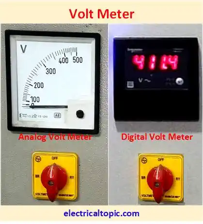
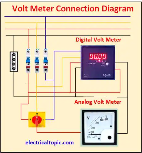
Volt meter is electrical instrument device which is used for measuring the system voltage. It is connected in electrical system as parallel. Single phase and three phase voltage are measured. LT supply voltage can be measured as directly connected into parallel. HT voltage can be measured with the help of potential transformer. Now a days the digital type voltmeter are used a lot more but analog type voltmeter are also used as little bit less.

2 - Connection Diagram:

3 - Types of Volt Meter:
Digital type and analog type volt meter are used. Actually with the time the analog voltmeter are replacing in place of digital voltmeter. The details are given below mentioned.
Analog Volt Meter
In analog voltmeter a pointer is moved across the scale which is proportional to the voltage of the system. Three type analog voltmeter are average reading, true RMS reading, sampling type. Overload indication is not available. It can not be programmed and its speed is low as per digital.
- Moving coil voltmeter
- Moving iron voltmeter
- Electrostatic volt meter
Digital Volt Meter
With the time the digital voltmeter are using as more. Its accuracy is good against analog meter. It has numerical display for voltage. It is two type like as ramp type and integrated type. It can be programmed as per requirements. Single phase and three phase voltmeter are available.
- Integrating digital volt meter
- Ramp type digital voltmeter
- Successive approximation digital voltmeter
- Continuous balance digital volt meter
4 - Working Principle:
1- Analog Volt Meter:
Basically three types analog voltmeter are used as moving coil, moving iron and electrostatic. The moving
coil volt meter is also categorized as two types, one is permanent magnetic type and dynamo magnetic type.
- Input supply is received by magnetic coil in analog meter.
- A flux is produced by magnetic coil and received by pointer mechanism.
- Pointer mechanism is moved on display dial ratings.
- Voltage can be read by easily on display.
2- Digital Volt Meter
DVM is a numerical display instrument device which is used for voltage measuring. Now we are going to discuss about digital volt meter working principle.
- A voltage signal is received by pulse generator as input form.
- Pulse generator output is received by AND gate one side input and other side input of AND gate is pulse sequence.
- AND gate output as positive trigger pulse is received by inverter as input form .
- Inverter output as form of trigger pulse is received in input form by counter device where the counter device counts the positive trigger.
- Counter device output is received by display device where the value of voltage is displayed.
5 - Applications of Volt Meter:
Volt meter is used where the voltage knowing is must. Now a days it is using in domestic, industries, electrical generation, transmission and distribution. For LT side voltage meter is connected as parallel and HT side voltage can be found with the help of potential meter.