Automatic Power Factor Control(APFC) Panel
Wiring Diagram, Components and working principle.
1 - Power Factor Control Panel:
Automatic power factor control panel (APFC) is used for maintaining the power factor .98 or .99 which is adjusted automaticly through APFC relay by switching on and switching of capacitor bank in electrical system. APFC panel is used in industries for improving power factor because the inductive load are used as much more. It has a microprocessor type controller which start the capacitors one by one after increasing RKVA. All capacitors are connected with busbar as parallel and they all are switched on one or more as per requirement. capacitors

2 - Wiring Diagram of APFC panel:
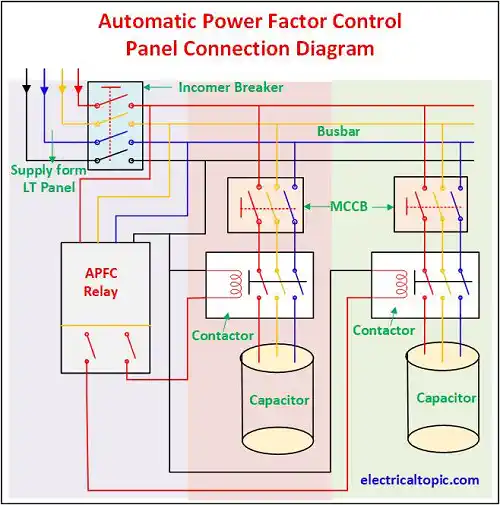
3 - Components of power factor control panel.
1- Incomer Section:
A- Air circuit breaker:
APFC panel power supply is received from LT panel. ACB is used for making and breaking incoming power where ACB incomer supply is connected with LT panel and outgoing is connected with APFC panel busbar.
B- Measuring Meter
Many types meters are used in panel like as Analog meter and digital meters. Amp meter, volt meter, multi function meter, energy meter are used for measuring the parameters. It all can be used digital or Analog as per requirement.
C- Indicators
Indicators are used for knowing the status of panel operation.Difference type indicators are used with different color.
- R Phase.
- Y Phase.
- B Phase.
- Breaker ON.
- Breaker OFF.
- Breaker Trip.
2- Automatic Power Factor Controlling Relay:
APFC relay are used for control and monitoring to the capacitor. If the power factor got below 9.8 then it provides the connecting signal to the capacitors for connecting with busbar. If the power factor is maintained then it again sends a signal for disconnecting the capacitor from busbar.
3- Capacitor Bank Section:
Capacitor
Three phase capacitor are used for improving power factor. They all are connected with parallel condition in main panel busbar. Capacitor are available as 30, 50 and 60 KVAR.
Contactor
Contactors are used for connecting and disconnecting capacitor to the busbar. Contactor coil is hold when a signal is received from APFC relay.
Push button and indicators
ON and OFF Push button are used for capacitor switch on in manually condition. ON and OFF indicators are
also used for knowing the status of capacitor.