Earth Pit Resistance Test
Testing Diagram and Testing Procedure.
1- Earth Pit Resistance Test:
Earth resistance test should be carried out in timely as quarterly basis because with time the lack of moisture the soil resistivity can be increase as above 2 ohm. High resistance is the cause of interruption of current flow in quickly so resistance value should be less then 2 ohm. So in tis way the earth resistance test is required in timely.
The earth electrode resistance value should be less than 2 ohm. For better performance of earth electrode, the value of earth resistance should be minimum if the value is more than 2 ohm then short circuit current will not flow quickly. During fault condition current should be travel quickly into ground through earth electrode. So in this way we can say earth resistance value should be check timely as quarterly basis.
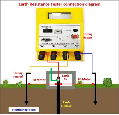
2- Earth Pit Testing diagram:

3- Earth Pit Testing Kit:
Testing kit is the set of testing meter and other supported accessories which below mentioned.
- Testing meter: 1 Nos.
- Iron electrode(spike): 2 Nos.
- Hammer: 1 nos
- Testing wire: 1.5 Sq.mm 30 meters or according requirement.
- Measuring tap : 20 Mtrs.
4- Safety guidelines before earth pit Resistance Test:
- Earth electrode should be disconnect from electrical panel or equipment.
- Testing iron electrode distance should be 10 mtrs between testing electrode and earth electrode.
- Testing meter battery should be fully charged because due ot low battery the testing value can be hampered.
- Earth electrode thimble should be clean properly with emery paper.
5- Earth Pit Testing Procedure:
- disconnect the panel earth wire from earth electrode in earth pit.
- Measure the 10 mtrs distance from earth pit left side and opposite right side.
- Put and insert testing iron electrode P2 inside the ground at the point of 10 mtrs distance left side from earth pit.
- Put and insert testing iron electrode E2 inside the ground at the point of 10 mtrs distance right side from earth pit.
- Testing meter P1 and E1 both points are connected to the ground earth electrode.
- Testing meter P2 point is connected with P2 testing electrode which has left side grounded from earth pit.
- Testing meter E2 point is connected with E2 testing electrode which has right side grounded from earth pit.
- After all connections the red tes button of meter is pressed continue just second.
- Read the measured value on meter display.
- If the value or resistance is below 2 ohm then the earth pit electrode is normal.
- The tested value is more than 2 ohm then the after rechecking all connections the testing procedure should be done again.
6- Eath Pit test Value Observation:
- Testing parameters are noted down.
- If the resistance value is below 1 ohm then it is perfect.
- If the resistance value is below 2 ohm then is satisfactory.>
- If the value is above 2 ohm then it is maintenance required.
- If the value is more than 5 ohm then it is re Construction required.