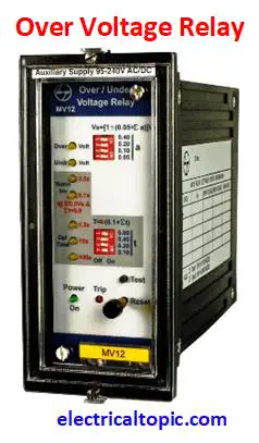
Over Voltage Relay
Working principle, Wiring diagram and ANSI Code.
1 - Over voltage relay:

Over voltage relay is an electrical protection device which is used for prevention of exceeding system
voltage and operated after crossing pre set value of voltage and time then a tripping signal is provided to
the circuit breaker tripping coil. It is used in transformer outgoing isolation panel or LT panel or
feeder panel for controlling over voltage.
Over voltage relay continue monitors the default voltage level
of system. If the voltage level is exceed pre set voltage limit then system will be tripped.
2 - Why it is used?
Over voltage condition is very dangerous in system voltage. Due to over voltage the insulation which is used
on wire, cable, windings, may be failure, burn or heat. It means over voltage is very dangerous for equipment
health. So over voltage relay is used.
For exp: Default system voltage is 415V and +5% voltage variation is tolerated. If above >5% voltage can be
dangerous for system. So it is the important reason for using Over voltage relay.
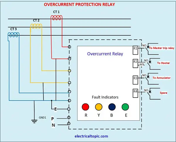
3 - Connection diagram of over voltage relay.

4 - Working principle of over voltage relay.
Over voltage preset value of + 5% multiply of system voltage and time 0.1 to 1.6 second can be adjusted as
per requirement. If the voltage is
increased pre set value and time limit then Over voltage relay provides a tripping signal to the circuit
breaker tripping coil resultant tripping coil pushes to the trip mechanical latch. After tripping, the Over
voltage relay provides us alarm, red indication on display screen and reset push button comes out side.
Again for normal
operation of OVR, we will have to press the reset push button so that system could be work normally. It is
microprocessor based relay and it is so important for prevention of over voltage.
5 - Relay setting parameters:
| Sr.No. | Parameters | Setting range |
|---|---|---|
| 1 | Voltage | : 110V, 220V or 415V |
| 2 | frequency | : 50, +/- 2.5 % |
| 3 | Auxiliary supply |
: 24V to 110V AC/DC or 95V to 240V AC/DC |
| 4 | Over Voltage relay setting | : 105% - 180% of system voltage (in steps of 5%) |
| 5 | Time | : 0.1 to 1.6 in steps of 0.1 |
| 6 | Pickup Current | : Same as set current |
| 7 | Reset Voltage | : 90% - 95% of set voltage. |
| 8 | Reset time | : 0.1- 10Sec in steps of 0.1Sec or Less than 50ms |
| 9 | Output volt for breaker trip coil. | : 240 volt AC or 30V DC |
| 10 | Indication LED. | :1- Supply on, 2- Over voltage, 3- Blink LED after crossing limit. |
| 11 | Output relay contact. | :1- for Alarm, 2- for tripping coil. |